Interference, Diffraction, and Polarization Name:_______________________
Partner(s):__________________________________________________________
Instructor Notes: Attach the linear
translator to the optics bench close to the 0-cm end and set the aperture
bracket to 1.
A. Double-Slit Interference
Purpose: To observe double-slit interference pattern and measure the wavelength of light.
Apparatus: Light sensor w/aperture bracket & cable, diode laser w/power adapter, multiple-slit set, optics bench w/linear translator, meter stick, rotary motion sensor, 750-interface, and PC.
Theory:
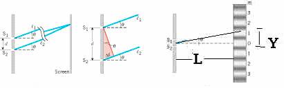
Bright fringes of a double-slit are given by (d is double-slit separation and λ is wavelength),
![]()
First bright fringe is given by,
![]()
![]() ;
(Y is fringe-width),
;
(Y is fringe-width),
![]()
Procedure:
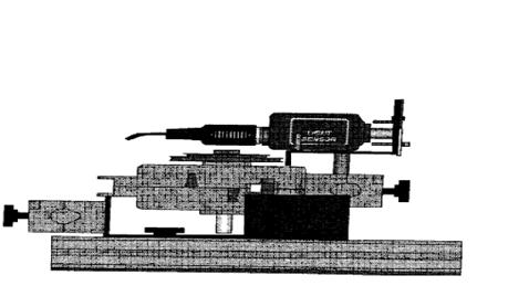
1. Place the optics bench w/linear translator on the laboratory table.
2. Remove the rack from the linear translator by unscrewing the two rack thumbscrews.
3. Insert the rack through the slot in the side of the rotary motion sensor,
step-pulley is facing up and the rod-clamp is facing the bench. Put the rack
back and tighten it with rack thumbscrews. 
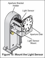
4. Attach the light sensor with aperture bracket to the rotary motion sensor as shown below.
5. Mount the diode laser on the other end, at the 100-cm mark of the optics
bench. 
6. Set the multiple slit to a double slit separation, d of 0.25 mm and place the double-slit at the 90-cm mark.
7. Plug in the power adapter for the laser.
8. Adjust the position of the light sensor so that the laser beam strikes in the middle of the aperture bracket-1.
9. Move the rotary motion sensor/light sensor so that the interference pattern is away from aperture bracket-1.
10. Connect the rotary motion sensor to digital channels 1 (black) and 2 (yellow).
11. Set the gain to 100 in the light sensor and connect it to analog channel A.
12. Open DataStudio, click Open Activity, click Library, click Physics Labs, and click P35 Diffraction.
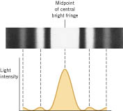
13. Open the Light Intensity versus Position graph display.
14. Click Start, and slowly and smoothly move the rotary/light sensor so that the whole interference pattern passes through aperture-1 of the light sensor.
15. Stop recording data and maximize the graph display.
16. Show the graph to the instructor.
17. Under the Data display double-click the 4th title, Light Intensity VS. Position and open the Data Properties window and change the precision to 5.
18. Measure the total width for multiple fringes using the smart tool, double-slit to screen distance (L) with a meter stick, and complete the data table.
19. Print a hardcopy of the interference pattern and Close DataStudio, without saving.
B. Single-Slit Diffraction
Purpose: To observe single-slit diffraction pattern and measure the wavelength of light.
Apparatus: Light sensor with aperture bracket, diode laser, single-slit set, optics bench, rotary motion sensor, linear translator, meter stick, 750-interface, and PC.
Theory:
|
|
|
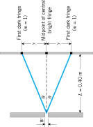
Dark fringes for the single-slit diffraction are given by (w is the
single-slit width and λ is wavelength),
![]()
For the first dark fringe (y is the half-width of the central dark fringe),
![]()
![]()
Procedure:
1. Remove the double-slit and replace it with a single-slit set to slit-width, w = 0.16 mm.
2. Open DataStudio, click Open Activity, click Library, click Physics Labs, and click P35 Diffraction.
3. Open the Light Intensity VS. Position graph display.
4. Click Start, and slowly and smoothly move the rotary/light sensor so that the whole diffraction pattern passes through the sensor.
5. Stop recording data, maximize the graph display, and show the graph to the instructor.
6. Under the Data display double-click the 4th title, Light Intensity VS. Position and open the Data Properties window and change the precision to 5.
7. Measure the width of the central bright fringe using the Smart Tool, single-slit to screen distance (L) with a meter stick, and complete the data table.
8. Print a hardcopy of the diffraction pattern and Close DataStudio, without saving.
DATA
A. Double-Slit Interference
# of fringes = N = _________
Width for the above # of fringes = _________________________________
Fringe-width = Y = __________
Double-Slit separation = d = _________
Double-Slit to Screen distance = L = __________
Wavelength (measured) = λ = dY/L = __________
Wavelength (accepted) = λ = ___________
% Error = ____________
B. Single-Slit Diffraction
Width for the central bright fringe = 2Y = _______________________________
Half-width for the central dark fringe = Y = ________
Single-Slit width = w = _________
Single-Slit to Screen distance = L = __________
Wavelength (measured) = λ = wY/L = __________
Wavelength (accepted) = λ = ___________
% Error = ____________
C. Polarization
Purpose: Verify Malus’ law of polarization.
Apparatus: Optics Bench, Diode laser, power
adapter for diode laser, Light Sensor with aperture bracket, Rotary Motion
Sensor, Allen wrench (7/64”),
Polarization kit with mounting bracket and belt, and Accessory Holder
w/2 Brass Screws.
Theory: Once
polarized light has been produced with a piece of polarizing material or with a
laser, it is possible to use a second polarizer to change the polarization
direction and simultaneously adjust the intensity of the light as shown in
Figure 24.21 of
your textbook. As in this picture the first piece of polarizing material is
called the polarizer, and the second piece is referred
to as the analyzer. The transmission axis of the
analyzer is oriented at an angle q relative to the transmission axis of the polarizer.
If the electric
field strength of the polarized light incident on the analyzer is E,
the field strength passing through is the component
parallel to the transmission axis, or E cos q. According to
Equation 24.5b,
the intensity is proportional to the square of the electric
field strength. Consequently, the average intensity of polarized light passing
through the analyzer is proportional to cos2q. Thus, both the
polarization direction and the intensity of the light can be adjusted by
rotating the transmission axis of the analyzer relative to that of the
polarizer. The average intensity ![]() of
the light leaving the analyzer, then, is
of
the light leaving the analyzer, then, is
|
(24.7) |
|
where ![]() is
the average intensity of the light entering the analyzer. Equation 24.7 is sometimes
called Malus’ law,
for it was discovered by the French engineer Etienne-Louis Malus
(1775–1812).
is
the average intensity of the light entering the analyzer. Equation 24.7 is sometimes
called Malus’ law,
for it was discovered by the French engineer Etienne-Louis Malus
(1775–1812).
|
Procedure:
- Remove the light sensor
with aperture bracket from the rotary motion sensor, which is attached to
the linear translator.
- Remove the rotary motion
sensor from the linear translator.
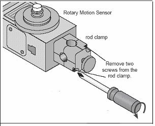
- Remove the rod clamp from
the rotary motion sensor by removing the two silver screws on the clamp
with the use of an Allen Wrench as shown below.
![]()
![]()

- Attach the rotary motion
sensor to the polarization kit as follows:
- Remove the plastic belt
and two thumbscrews from the polarization kit.
- Line up the holes from
mounting bracket with the holes of the rotary motion sensor and attach
the two thumbscrews as shown below. (Make
sure that the three-step pulley is facing in and the silver rod is
pointing out.)
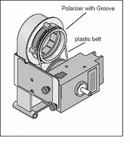
c. Place the plastic belt around the three-step
outer-pulley on the Rotary Motion Device and the groove on the polarizer as
shown above.
![]()
5. Attach the light sensor with the
aperture bracket to the accessory holder as follows:
- Remove the brass screws
from the accessory holder.
- Line up the screw holes
of the accessory holder with that of the Light Sensor.
- Using the 2 brass screws,
attach the Light Sensor to the accessory holder.
- Set the light sensor gain
to 1 and aperture disk to #6.
- Positioning of the
apparatus:
- Place the newly assembled
Light Sensor with aperture bracket at 50 cm.
- Place the Polarization Stand
at 30 cm.
- Place the Diode Laser at
100 cm, and turn it on.
- Connect the cable from the
Light sensor to port A, and the Rotary Motion
Sensor to ports 1 (yellow) and port 2 (black).
- Open Data Studio, click
Create Experiment, select light sensor, select digits display, and select
%Intensity.
- Click “Start” and rotate
the polarizer until the %intensity is a maximum. Record the maximum
%intensity transmitted.
________________________________
- Open activity P34 Malus’ Law.
- Double Click on the graph
display “%Intensity VS. Angular position.
- Click Start and rotate the
polarizer through one full turn.
- Show the graph display to
the instructor and if it is O.K print a hard copy.
- Describe below how your
results verify Malus’ law of polarization.