Name:_______________________________Date:_______________Time:____________
Course:_________________
_______________________________________________________________________
A. Ohm's Law Circuit
Purpose: To investigate Ohmís law and measure resistances.
Apparatus: Transformer (6 volt), rheostat (89 ohm), 6- connecting wires (banana plug), 2-alligator clips, 5-ohm resistor, 10-ohm resistor, light bulb, and 2- digital multi meters (DMM).
Theory: Georg Simon Ohm (1787-1854), a German physicist, discovered Ohmís law in 1826. This is an experimental law. Valid for both alternating current (ac) and direct current (dc) circuits.
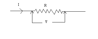
When you pass an electric current (I) through a resistance (R) there will be a an electric potential difference (V) created across the resistance.

Ohmís law gives a relationship between V , I and R as follows.
V = I R
Units: V------> volt (v), I------> ampere (A), R-----> ohm or v/A
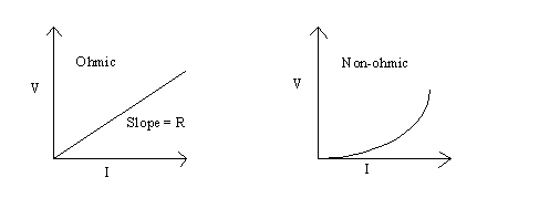
For ohmic resistances, V versus I is a linear relationship, and they have a constant resistance. Resistance can be calculated using the Ohmís law, R = V/I. The slope of the V versus I, line will also give the resistance, R.
For non-ohmic resistances, V versus I is a non-linear relationship, and they have a varying resistance. The resistance at a particular point can be calculated using Ohmís law, R = V/I, where V and I are the voltage and current at that point.
Electric power, P is given by the following equation:
Power = P = Voltage x Current.
In order to investigate Ohm's law you will construct a circuit and measure the current through and voltage across the following: 5-ohm resistor, 10-ohm resistor, and light bulb.
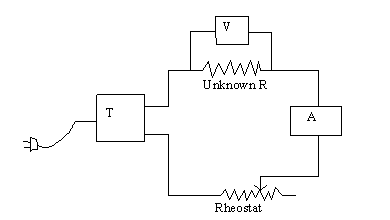
Circuit Diagram:
Caution: Leave the power cord unplugged. Plug it in only after your circuit is checked by the instructor.
Procedure:
1. First connect the following in a series circuit
as shown below:
Transformer (T), Rheostat, DMM as Ammeter (A), and unknown R
(5-ohm
resistor).
Use COM and A on a 2A scale, for the
Ammeter.
2. Now connect the second DMM across the unknown R as shown below. Use COM and V on a 20-v range.
3. Call the instructor to check the
circuit.
DATA: Unknown resistance: 5-ohm resistor.
Set the current, measure the voltage, and then calculate R. (Include units for V & R)
|
Current, I (A) |
Voltage, V(__) |
Resistance, R(__) |
|
0 |
0 |
XXXXXXXXX |
|
0.05 |
- |
- |
|
0.10 |
- |
- |
|
0.15 |
- |
- |
|
0.20 |
- |
- |
|
0.25 |
- |
- |
|
0.30 |
- |
- |
|
0.35 |
- |
- |
| 0.40 | - | - |
| 0.45 | - | - |
| 0.50 | - | - |
Look at the resistance values and predict the V versus I relationship for the 5-ohm resistor.
____________________________________________________________________
Plot V versus I, and determine the slope. Slope = _________________________
DATA: Unknown
resistance: 10-ohm resistor.
Set the current, measure the voltage, and then calculate R. (Include units for V & R)
|
Current, I (A) |
Voltage, V(__) |
Resistance, R(__) |
|
0 |
0 |
XXXXXXXXX |
|
0.05 |
- |
- |
|
0.10 |
- |
- |
|
0.15 |
- |
- |
|
0.20 |
- |
- |
|
0.25 |
- |
- |
|
0.30 |
- |
- |
|
0.35 |
- |
- |
| 0.40 | - | - |
| 0.45 | - | - |
| 0.50 | - | - |
Look at the resistance values and predict the V versus I relationship for the 10-ohm resistor.
____________________________________________________________________
Add this plot of V versus I, to the earlier graph and determine the slope. Slope = __________________
Print a hard-copy.
DATA: Unknown resistance, LIGHT
BULB.
Set the current, measure the voltage, and then calculate R & P. (Include units for V, R, and P)
|
Current, I (A) |
Voltage, V(__) |
Resistance, R(__) |
Power, P(__) |
|
0 |
0 |
XXXXXXXXXX |
- |
|
0.05 |
- |
- |
- |
|
0.10 |
- |
- |
- |
|
0.15 |
- |
- |
- |
|
0.20 |
- |
- |
- |
|
0.25 |
- |
- |
- |
|
0.30 |
- |
- |
- |
|
0.35 |
- |
- |
- |
|
0.40 |
- |
- |
- |
|
0.45 |
- |
- |
- |
|
0.50 |
- |
- |
- |
|
0.55 |
- |
- |
- |
| 0.60 | - | - | - |
Look at the resistance values and predict the V versus I relationship for the light bulb.
____________________________________________________________________
Plot V versus I, on a separate graph and print a hard-copy.
Conclusion:
B. Circuits with Resistors and Capacitors
Purpose: To investigate various combinations of resistors and capacitors.
Apparatus: Three resistors, 3 capacitors, circuit board, digital multimeter, and 2-banana plug wires w/alligator clip on one end.
A. Resistors:
1. Determine the values of the three resistors using the resistor color code.
2. Measure the values of the three resistors using the digital multimeter (DMM).
3. Observe the tolerance values and them in the data table.
|
R1 |
R2 |
R3 | |
| From resistor color code | |||
| From digital multi- meter | |||
| Tolerance |
4. When two or more resistances are connected in series the equivalent resistance, R is give by;
![]()
When two or more resistances are connected in parallel the equivalent resistance, R is give by;
![]()
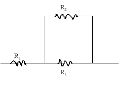
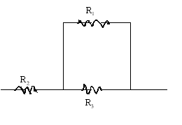
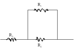
5. Connect the three resistors as shown below and measure the equivalent resistance.
6. Also calculate the equivalent resistance values using the DMM values for individual resistances.
|
Resistor combination |
Resistance values | |
| Measured | Calculated | |
| All in series |
| |
| All in parallel |
| |
 |
||
 |
||
 |
||
B. Capacitors:
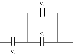
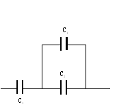
When two or more capacitors are connected in series the equivalent capacitance, C is give by;
![]()
When two or more capacitors are connected in parallel the equivalent capacitance, C is give by;
![]() Measured values: C1= _______
C2=_______ C3=_______
Measured values: C1= _______
C2=_______ C3=_______
|
Capacitor combination |
Capacitance values | |
| Measured | Calculated | |
| All in series |
| |
| All in parallel |
| |
 |
||
 |
||
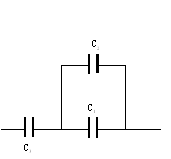 |
||