Circuits Name:_______________________________________
Partner(s):______________________Date:______Time:_______Course:___________
A. Ohm's Law
Purpose: To investigate Ohm’s law and measure resistances.
Apparatus: DC power supply, rheostat (89 ohm), 6- connecting wires (banana plug), 2-alligator clips, 5-ohm resistor, 10-ohm resistor, light bulb (6.3A,0.5A), and 2- digital multi meters (DMM).
Procedure:
1. Call the instructor to check the circuit.
2. Set the current, measure the voltage, and then calculate R.
DATA: Unknown resistance: 5-ohm resistor.
|
Current, I (A) |
Voltage, V( ) |
Resistance, R( ) |
|
0 |
0 |
XXXXXXXXX |
|
0.05 |
- |
- |
|
0.10 |
- |
- |
|
0.15 |
- |
- |
|
0.20 |
- |
- |
|
0.25 |
- |
- |
|
0.30 |
- |
- |
|
0.35 |
- |
- |
|
0.40 |
- |
- |
3. Turn the dial in the power supply to zero current & voltage.
4. Look at the resistance values and predict the V versus I relationship for the 5-ohm resistor.
____________________________________________________________________
5. Plot V versus I, and determine the slope. Slope = _________________________
DATA: Unknown resistance: 10-ohm resistor.
6. Set the current, measure the voltage, and then calculate R.
|
Current, I (A) |
Voltage, V( ) |
Resistance, R( ) |
|
0 |
0 |
XXXXXXXXX |
|
0.05 |
- |
- |
|
0.10 |
- |
- |
|
0.15 |
- |
- |
|
0.20 |
- |
- |
|
0.25 |
- |
- |
|
0.30 |
- |
- |
|
0.35 |
- |
- |
|
0.40 |
- |
- |
7. Turn the dial in the power supply to zero current & voltage.
8. Look at the resistance values and predict the V versus I relationship for the 10-ohm resistor.
____________________________________________________________________
9. Add this plot of V versus I, to the earlier graph and determine the slope.
Slope = __________________
10. Print a hard-copy of your graphs.
DATA: Unknown resistance, LIGHT BULB.
11. Set the current, measure the voltage, and then calculate R & P. (Include units for V, R, and P)
|
Current, I (A) |
Voltage, V(__) |
Resistance, R(__) |
Power, P(__) |
|
0 |
0 |
XXXXXXXXXX |
- |
|
0.01 |
- |
- |
- |
|
0.025 |
- |
- |
- |
|
0.05 |
- |
- |
- |
|
0.075 |
- |
- |
- |
|
0.10 |
- |
- |
- |
|
0.15 |
- |
- |
- |
|
0.20 |
- |
- |
- |
|
0.25 |
- |
- |
- |
|
0.30 |
- |
- |
- |
|
0.35 |
- |
- |
- |
12. Look at the resistance values and predict the V versus I relationship for the light bulb.
____________________________________________________________________
13. Plot V versus I, on a separate graph and print a hard-copy.
14. Attach your graphs, write a conclusion, and attach it too.
B. Circuits with Resistors and Capacitors
Purpose: To investigate various combinations of resistors and capacitors.
Apparatus: Three resistors, 3 capacitors, circuit board, digital multimeter, and 2-banana plug wires w/alligator clip on one end.
A. Resistors:
1. Determine the values of the three resistors using the resistor color code.
2. Measure the values of the three resistors using the digital multimeter (DMM) as shown below.
3. Observe the tolerance values and record them in the data table.
|
|
R1 |
R2 |
R3 |
|
From resistor color code |
|
|
|
|
From digital multi- meter |
|
|
|
|
Tolerance |
|
|
|
When two or more resistances are connected in series the equivalent
resistance, RS is given by; ![]()
When two or more resistances are connected in parallel the equivalent
resistance, RP is given by; ![]()
4. Connect the three resistors as shown below and measure the equivalent resistance.
5. Also calculate the equivalent resistance values using the DMM values for individual resistances.
Data:
|
Resistor combination |
Resistance values |
|
|
Measured |
Calculated |
|
|
|
|
|
|
All in parallel |
|
|
|
|
|
|
|
|
|
|
|
|
|
|


B. Capacitors:
When two or more capacitors are connected in series the equivalent capacitance, CS is given by;
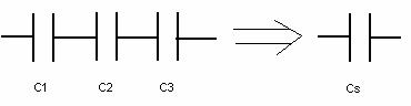
![]()
When two or more capacitors are connected in parallel the equivalent capacitance, CP is given by;
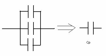
![]()
6. Measure the values of the three capacitors using the digital multimeter
(DMM) as shown here.
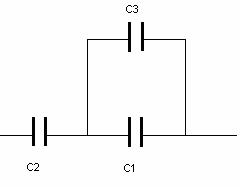
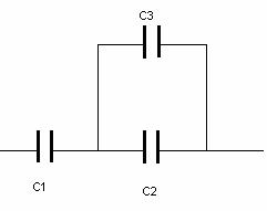
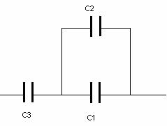
7. Connect the three capacitors as shown below and measure the equivalent capacitance.
8. Also calculate the equivalent capacitance values.
DATA: Capacitors
Measured values: C1= _______ C2 = _______ C3 =__________
|
Capacitor combination |
Capacitance values |
|
|
Measured |
Calculated |
|
|
All in series |
|
|
|
All in parallel |
|
|
|
|
|
|
|
|
|
|
|
|
|
|