RC Circuits
Name:_________________________________ Course:_____________ Time:__________
Partners:____________________________________________________________________
Purpose::
To observe the voltage as a function of time across a capacitor in a simple, series RC circuit and determine the capacitance.
Apparatus:: PC w/interface, voltage sensor, capacitor, decade resistance box, and banana-plug wires (3).
Theory::

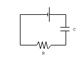
When a DC voltage source is connected across an uncharged capacitor, the rate at which the capacitor charges up decreases as time passes. At first, the capacitor is easy to charge because there is very little charge on the capacitor plates. But as charge accumulates on the plates, the voltage source must “ do more work” to move additional charges onto the plates because the plates already have charges of the same sign on them. As a result, the capacitor charges exponentially, quickly at the beginning and more slowly as the capacitor becomes fully charged. The charge on the plates at any time is given by:
![]()
Where q0 is the maximum charge on the plates and τ = RC, the capacitive time constant. Taking the extreme limits, notice that when t = 0, q = 0 which means that there is not any charge on the plates initially. Also notice that when t goes to infinity, q goes to q0, which means it takes an infinite amount of time to completely charge the capacitor. In this activity the charge on the capacitor will be measured indirectly by measuring the voltage across the capacitor since these two values are proportional to each other, q = cV.
The time it takes to charge the capacitor to half full is called the half-life and is related to the capacitive time constant in the following way:
![]()
You will measure half-life for various values of resistances. By graphing half-life versus resistance, you can determine the capacitance from the slope.
 |
CAPACITOR VOLTAGE CAPACITOR CHARGE |
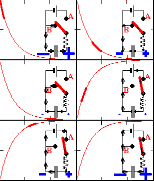
The above applet shows the capacitor voltage as a function of time during charging and discharging.
Procedure:
A. Observing the output signal:
1. Plug in the voltage sensor to channel B.
2. Open "DataStudio", select "Open Activity", select "Library", select "Physics Labs", and select "P50-RC circuits".
3. Double click "Output Voltage" in the Data Window (upper left corner), and record the properties of the out put signal of the signal generator.
Type: ______________________________________
Amplitude = _____________________Frequency = ______________
4. Close the signal generator window.
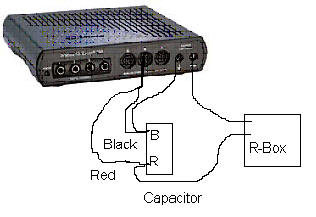
5. Connect the voltage sensor wires to out put of the interface box, black to
![]() and red to
and red to
![]() .
.
6. Double-click the Voltage Graph graph display, and click start.
7. At the end of data collection, click the "Scale to fit" button, to maximize the display.
8. Observe the out put signal, and measure the amplitude and period. Calculate the frequency.
Amplitude = _____________Period = _____________Frequency = ______________
B. RC circuit:
1. Disconnect the voltage sensor wires from the output.
2. Connect the output, decade resistance box, and capacitor in series. Connect the voltage sensor across the capacitor. Set the resistance to 50 ohm.

3. Remove the last data run, by Clicking "Experiment" and clicking "Remove Last Data Run".
4. Click "Start".
5. The data collection will stop automatically. You should see two or three peaks.
6. Click the "Scale to fit" button. The second peak will display the charging of the capacitor from zero voltage to 4 volt.
7. Click the Smart Tool button and determine the time for zero voltage for the second peak. Then, move up the smart tool and determine the time for half-the peak voltage, 2 volt. If you cannot get 2 volt, record the times for values close to 2 volt and get the average.
8. Repeat your measurements for other values of the resistances and complete the data table.
9. Plot a graph, half-life versus R, determine the slope, and calculate the capacitance.
10. Print a hard-copy of your plot.
DATA
Maximum voltage = 4 volt, Half the maximum voltage = 2 volt.
|
R (ohm) |
Time for V=0 | Time for > 2 V | Time for < 2 V | Ave.Time for 2V | half-life (s) |
| 50 | |||||
| 100 | |||||
| 150 | |||||
| 200 | |||||
| 250 | |||||
| 300 | |||||
| 350 | |||||
| 400 | |||||
| 450 | |||||
| 500 |
Show your work to calculate the capacitance from the slope: