Name:__________________________Date:_______________Time:___________Course:__________
Electrostatic Charge and
Fields
A. Electrostatic Charge
Purpose: Investigate the charging of a metal container by contact and by induction using a charge sensor.
Apparatus: PC w/interface, charge sensor, cable assembly, glass rod, hard-rubber rod, fur, and calorimeter: jacket & lid.
You will use a charge sensor to determine the polarity of the charge producers. Then measure the amount of charge transferred to a metal container by contact and by induction.
Procedure:
a. Charge Polarity
1. Connect the charge sensor to analog channel A, and set the gain to 1.
2. Connect the cable assembly to the BNC port on the sensor. To do this: Line up the connector on the end of the cable with the pin on the BNC port. Push the connector onto the port and then twist the connector clockwise about one-quarter turn until it clicks into place.
3. Connect the alligator clips (red and black) of the cable assembly to the calorimeter jacket, place the lid on the table, and place the calorimeter jacket on the lid.
4. Open "DataStudio", select "Open Activity", select "Library", select "Physics Labs", and select P29-Charge.
5. Double-Click on the Graph display.
6. Press the 'zero' button on the charge sensor to discharge the sensor.
7. Un-ground the jacket by removing the black alligator clip from the calorimeter jacket and leave it not connected.
8. Click "Start", if the voltage is not zero, press the zero button on the charge sensor, again.
9. Charge the hard-rubber rod with fur and lower the rod inside the jacket without touching the inside, and hold it there for few seconds and then remove it. Observe the graph display.
10. If the voltage didn't come back to zero, ground the calorimeter jacket and re-zero the charge sensor. Un-ground the jacket.
11. Charge the glass-rod with fur (use the smooth side for rubbing and the rough side for holding) and lower the rod inside the jacket without touching the inside, and hold it there for few seconds and remove it. Observe the graph display.
12. Stop recording data.
Charge Polarity Data: (Look at the Charge Polarity graph and answer the following questions)
a. What polarity is the charge, on the rubber rod?__________on the glass rod?___________
b. What is the peak value of voltage produced by the rubber
rod?________by the glass rod?__________
(Use the smart tool to read)
13. Delete the data from the graph display, and get a blank graph display.
b. Charging by Contact
1. Click "Start", if the voltage is not zero, ground the jacket and press the zero button on the charge sensor, again. Un-ground the jacket.
2. Charge the hard-rubber rod with fur and lower the rod inside the jacket, and make contact inside at many places, while turning the rod. The rod is an insulator, so you need to move the rod and make contact to transfer the charge. Just touching it won't transfer much charge. Observe the graph display.
3. Ground the jacket with the black alligator clip and then un-ground it. If the voltage is not zero, press the zero button on the charge sensor, again. Data recording is still going on.
4. Charge the glass-rod with fur and lower the rod inside the jacket, and make contact inside at many places, while turning the rod. The rod is an insulator, so you need to move the rod and make contact to transfer the charge. Just touching it won't transfer much charge. Observe the graph display.
5. Ground the jacket with the black alligator clip and then un-ground it. If the voltage is not zero, press the zero button on the charge sensor, again.
6. Stop recording data.
Charging by Contact Data: (Look at the Charging by Contact graph and answer the following questions)
a. What is the value of voltage produced by the transfer charge from rubber rod?________
b. What is the value of voltage produced by the transfer charge from glass rod?________
7. Delete the data from the graph display.
c. Charging By Induction
1. Click "Start", if the voltage is not zero, press the zero button on the charge sensor, again.
2. Charge the hard-rubber rod with fur and lower the rod inside the jacket without touching the inside, and hold it there. While holding the rod inside, ground the jacket, then remove the ground, and then remove the rod. Observe the graph display.
3. Ground the jacket with the black alligator clip and then un-ground it. If the voltage is not zero, press the zero button on the charge sensor, again.
4. Stop recording data.
Charging By Induction Data: (Look at the Charging by Induction graph and answer the following questions)
a. What is the peak value of voltage produced by the rubber rod, while it is inside?________
b. What is the peak-value of voltage produced by the induced charge from rubber rod?_________
c. What is the polarity of the induced charge?___________
d. Draw a series of diagrams, showing how you will charge
a conducting object, by induction?
B. Electric potential lines: (The instruction on this section has been
changed. It has been simplified. Please
listen to your instructor and follow his or her demonstration)
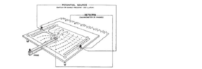
Connect the battery terminals to the power supply. Connect the probe to “A”. Select the voltage sensor (last in the list) and the click start. The instructor will show you how to map the equipotential lines.
Purpose: To map the electric field lines by plotting the equipotential lines.
Apparatus: field mapping board, field plates (2), power supply, voltage sensor, wires, and probe.
Procedure:
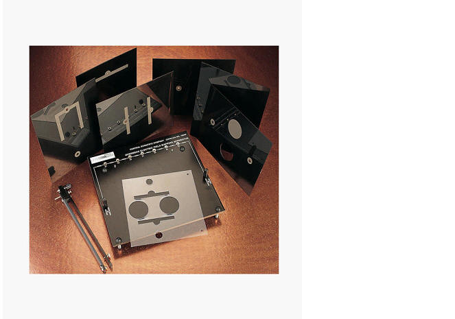
1. Place the field plate (choose the simpler patter first) on the underside of the field-mapping board and secure it to the conducting terminals using the two thumb screws provided.
2. Fasten a sheet of paper on the upper-side of the field-mapping board. (The paper is secured by depressing the board from either side and slipping the paper under the four rubber bumpers.)
3. Place the design template on the two projections (template guides) above the paper and trace the corresponding template design (electrodes) on the paper.
4. Connect the power source to the electrodes and mark the polarities of the electrodes.
5. Connect the detector to the computer via “A”
6. Carefully slide the probe with the ball end facing the underside of the field-mapping board and position it between the electrodes. Make sure the leg of the probe slides on the table top for balance of the probe.
7. Move the probe toward one of the electrodes until you get no deflection on the galvanometer and draw a small circle through the hole on the probe.
8. Now move the probe about 1cm toward one side of the paper and find another point which gives you a null reading on the galvanometer. Repeat this until you have a series of points from one side of the paper to the other. Look for points closer if the line is curving sharply. Draw the equi-potential line by joining the series of points.
9. Now connect the galvanometer between another slot and the probe and repeat procedures 7 & 8. Continue until you have equipotential lines for all the slots.
10. Draw curves perpendicular to the equipotential lines. Name them as electric field lines.
11. Repeat procedures 1-10 for another field plate.
C. Magnetic Field Lines:
Purpose: To map the magnetic field lines of permanent magnets.
Apparatus: Two magnets: bar & horseshoe, compass, iron-fillings, piece of cardboard, and sheets of white paper.
Procedure:
1. Place a horseshoe magnet on the lab-table.
2. Place a piece of cardboard above the horseshoe magnet and then place a sheet of paper above the cardboard.
3. Sprinkle some iron-fillings on the paper close to the magnet and tap the cardboard. Roughly sketch the field-line pattern on the paper. Save the iron-fillings in the bottle.
4. Draw the magnetic field lines of the horseshoe magnet using a compass.
5. Repeat 1-4 for a bar magnet.